The Tipo 61 Maserati “Birdcage” was a winning car under the right circumstances in its brief competitive lifespan from mid-1959 into 1961. Light weight was its major advantage, with the complex tubular chassis structure that spawned the “Birdcage” name being the main factor. It also had excellent disc brakes, licensed from Girling, and very good suspension and steering, relative to the competition. Its body was designed for minimal frontal area, so even though it had a four cylinder engine, it was capable of perhaps 170 mph.
The designers paid close attention to details of lightness, for example, all of the large suspension pivot bolts were hollow. Ancillary engine castings were magnesium, as were the transaxle cases and the steering rack. The thin aluminum bodywork was fragile enough to suffer thumb prints from a gentle push down the pit lane, all in search of minimal mass.
But the quest for lightness often decreases the safety margin, and there were numerous DNF’s due to broken parts, whether in the chassis, engine or transmission.
The gearbox, rear-mounted and integrated with the final drive as a transaxle, was both one of the heaviest components in the car and also the most fragile.

Transverse Shafts Long Before the Competition
Maserati’s transaxle design was, like other items crafted by engineer Giulio Alfieri’s team in Modena, way ahead of its time. Most transaxles of the period had longitudinal shafts, typically with the ring and pinion at the front, centered on the halfshafts, with all of the weight of the gear sets hanging out behind the axle. That increases the polar moment of the car; more weight out towards the ends requires more effort to pivot the car around its center.
I spent some time with a Ferrari 312 Formula One car, from early on when they had just began to sprout wings. It was a V12 car, not a flat 12, and it had a huge longitudinal box hanging way out back. Later, in the ’70’s Ferrari built the 312T, which had transverse shafts in its gearbox, to reduce polar moment.


Maserati used transverse shafts in the 250F Grand Prix machine as early as 1955, and that gearbox was the basis for the T61, a few years later.
Massive Gears for Substantial Torque
The Birdcage’s big 2.9 liter engine made giant heaps of torque, which required a robust set of gears to get it to the 6.5″ rear tires. Despite the magnesium cases, the transaxle for a Maserati Birdcage is a heavy lump of metal. Just the bevel gear set on the input shafts, the parts that that change direction from the longitudinal driveshaft to the transversely oriented gear sets, is a serious chunk of steel.

This article assumes some familiarity with gearbox terminology. If you want a refresher, here are two concise explanations:
- How a Manual Transmission Works, howstuffworks.com
- How a Gearbox Works, mandttransmissions.co.uk
The shafts that carry the gears in the T61 box are large diameter and hollow. The layshaft that holds the fixed gears has a big double-row ball bearing on the outer end, with a single-row ball bearing inboard of the gears and a roller bearing on the outboard end to allow the shaft to float as the case grows with heat, and they do get hot!

The above image is taken looking towards the front of the main gearcase, with the top case half removed. It illustrates the general layout, with the long shaft at the bottom being the layshaft, or countershaft to some, with the gears splined onto the shaft and secured by the small ring nut on the left end. This can also be called the input shaft, as it always spins at the same speed relative to engine RPM, determined by the gear ratio of the bevel set.
You can see that the roller bearing on the far end has a wire in a groove that locates it into the case, while the ball bearing on the inboard side is clamped by the top half of the case to hold its position. The shaft location, side to side, is set by the large double row bearing on the other end of the shaft that lives in the side cover (already removed in this image).
The mainshaft is the upper shaft, carrying the driven gears on the output side, the gears engaging with the shaft via dog rings that are moved by shift forks.
The thin gear to the left of the image is reverse, then the largest gear is first, then second, third, fourth and fifth. It should be noted that reverse was not designed to carry much load, and new Birdcage drivers need to be made aware that it is very fragile.
The extra wide gear to the far right of the bearing is the output gear for the final drive set. Note that it is hung off the case, next to one ball bearing, essentially in single shear loading. A longer shaft with another bearing outboard would have made it far stronger, in double shear. In my opinion, this is the biggest design flaw of this gearbox.

The next image shows the right side of the box, with the layshaft at the front of the case and the 1st/reverse shift fork on the end of the mainshaft. You can see the other two shift rail ends for 2nd/3rd and 4th/5th. The bronze hub below the layshaft is for the reverse gear idler, which is engaged when the 1st/reverse fork is moved to the right.
Changing Gears and Changing Parts
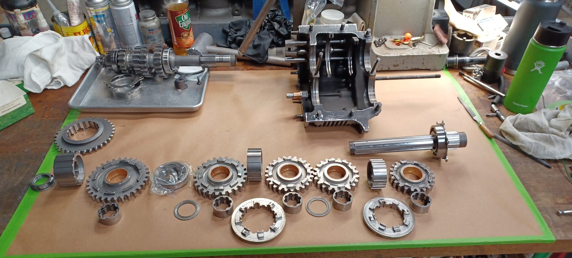
The thing that makes these Maserati boxes complicated to work on, more so than a Hewland, for example, is that the parts available for these are manufactured in very low volumes, and they are never direct replacements. If you have to replace a dog ring or a gear because the engaging dogs are worn out (a regular service item in a racing box), you are going to have to re-shim the stack. Meaning the new parts will not mesh the same as the previous parts, and the spacing will have to be corrected. More about that in part 2.

This next image is from the rear and illustrates the shift rails and detents. The top rail shifts 4/5, the middle rail shifts 2/3 and the bottom rail shifts 1/R. The three springs on the right push steel balls into the detents in the rails that control the shift fork position. The three holes to the right of the springs access three more springs and balls that push into the detents on the back side of the rail. This design allows for very short throws between shifts.
Buried in the left side of the casting, not visible from this angle, is the shift interlock mechanism. A pair of balls and a pin is moved by the shafts so that neighboring shafts are locked and cannot be accidentally moved while one gear is already engaged. That would result in the shafts locking together, and a seized box, with locked rear tires as a result, and no way to unlock them. No bueno! I heard an entertaining tale of just such an incident that occurred some years before I came to work at Reilly’s… A Birdcage was out being tested on Paradise drive, when the gearbox jammed in two gears, and the car left twin black stripes as the rear wheels skidded down the road, narrowly escaping an expensive interaction with the cars parked at the roadside. It is crucial to assemble the interlock correctly.

Transmitting Torque to the Wheels
Coming around to the left side of the box, we see the final drive output gear, and below it the ends of the shift rails poking out of the case. The hole in the casting above the top rail is the port that the interlock mechanism fits into. Between the final drive gear and the case is a plate that secures the ball bearing into the case, with safety wire locking the bolts. This bearing is in a steel case to help distribute the load into the soft magnesium. That illustrates how much more heavily loaded this bearing is compared to the other seven that are held without reinforcements. (Nine if you count the pair securing the ring gear in the top case).

Next, a view of that bearing carrier with its cover plate. These parts are frequently found to be worn out. The hole in the end of the shaft is the oil feed that sends pressurized gear lube to the mainshaft gear hubs. The oil pump is driven off the end of the layshaft, and draws oil through a screen in the sump. The pump outlet feeds the mainshaft as well as two jets at the top of the final drive, showering the big main output gear. The plumbing is illustrated in the next image. The mainshaft gears have drillings to feed oil from the hubs to the gears’ meshing teeth.


The Final Drive
The output gear, which would be called the ring gear in a conventional axle, lives on a differential carrier above the mainshaft. Two large diameter ball bearings carry the ZF-style differential that uses chicklets between inner and outer tracks.
The factory diff is not adjustable and is very expensive to replace when the parts are worn out. I have installed a replacement in two T61 boxes, a unit made by UK company Gripper Differentials. This unit is adjustable by changing the belleville spring that compresses the clutch plates, and by changing the setup of the ramps that control the way the torque is applied.

A Maserati T61 factory-type differential using chicklets between inner and outer tracks. 
These tubes squirt oil to lubricate and cool the final drive gears; the aluminum baffle shields the vent pipes from excess oil. 
A Maserati T61 differential with the final drive gear, inverted in the top case. 
A Gripper diff carrier for the T61 Birdcage Maserati 
Gripper diff internals for the T61 Birdcage Maserati
And that’s a lap around the gearbox for a Birdcage Maserati. The next installment will cover some of the known weak spots and how to guard against failures. I’ll also share some of the tips and tricks of setting it up, and the entertaining dance required to get it in and out of the chassis.
Got any questions? Hit the comments below, or shoot me an email. Till next time, remember: Nothing’s Easy.
Leave a Reply