
Specification
- Year: 1948
- Make: Talbot Lago
- Model: T26 Grand Sport
- Body: Saoutchik
- Engine: 6 cyl, twin cam, pushrod, 2 valve
- Disp: 4500 cc
- Gears:
I started working on this project back in 2016 in Colorado, the start of a long and circuitous path. In a previous post, I explained some of the issues that helped make it a five year engine build…
One of the few upsides of a worldwide pandemic is that some events get postponed, which gives some folks more time to finish a project. The Talbot Lago Grand Sport class that was to be at the Pebble Beach Concours d’Elegance in 2020 was shuffled back two years, which was fortunate for this car. I began final assembly in May of 2020 and could conceivably have had it running by August, but typical delays were magnified by COVID-19 and I signed off on the completed engine in January of 2021.
Some Problems and a Detail or Two
In the period between the crankshaft being fitted and the engine coming off the test stand, a variety of challenges had to be overcome. For example, I had a cam bearing issue that took a couple of attempts to resolve, which led to the cams being removed and revealing that the lifters we had made were wearing badly. So the cams needed the lobes touched up while the lifters were sent out to be micro-polished and DLC finished (Diamond Like Carbon). Surprisingly, the best DLC company is in France, and it took took over 8 weeks to get them back.
The Talbot is a twin cam engine, but the cams are high in the iron block. Because the block needed so much welding to repair the cracks it had, the cam bores were re-machined when the motor was in the Berco line boring machine for the main bearing bores. We made new bronze cam bearings of the same style Talbot made, and I fitted them making certain the oil ports lined up. Theoretically, they are concentric to the newly bored cam tunnel in the block, so they would not need to be line-honed after installation.

Too Tight, or Not Round?
After the motor had gotten up to temperature on the test stand, it quickly started to shriek in distress and I shut it off. The cam bearing closest to the oil pump drive had started to tighten up. This was a pretty major hangup. We could only guess that the load that was put on the cam by the oil pump drive was making the cam lean harder on that one bearing journal. All the bearings had the same design clearance and only the one had a problem.
A non-stellar design feature of the engine was that the cam bearings were located by a threaded set screw, not just the press fit. So you could potentially tighten that screw too much and oval the bearing. On top of that, the set screw was intended to be invisible after installation… they were made long with a drive slot, then filed flush with the casting after tightening and painted over.
I torqued them to a minimum pinch, going by feel, using red Loctite to both seal the oil in and keep them from backing out. That made removing the one damaged bearing extra fun! I made a new bearing for that location and gave it a little more clearance, which solved the problem.

The yellow arrow points to the flush-filed set screw that secures the cam bearing. 
The dimple for the set screw was cut by hand in the side of the bushing after it was pressed into position. 
The cam bearing that started to seize and a new one behind it with a larger clearance. 
The tappets were refinished with a DLC surface after the first version wore prematurely.
Connecting Rods and 11 millimeter bolts
The rods were reconditioned original Talbot Lago parts, as Magnaflux testing showed no cracks in the nicely made pieces. Finding quality metric rod bolts of the length required was impossible, so the old 11mm bolts were replaced with 7/16″ MIL spec bolts that have a higher tensile strength than the originals. The shank diameter of this spec bolt is precision finished and slightly larger than the 11mm part, so the holes can be honed to preserve the cap alignment. The 12 point head is machined to mimic the originals D-shape and the thread end shortened to suit the ARP 12 point nuts. New small end bushes were fitted and new babbitt poured by Rod Gaffrey, machined by David Wallace.


Head gasket sealing
The Talbot’s cylinder liners are wet-type, meaning that they seal into a spigot at the bottom with two rubber O-rings, and seat into a recess in the top of the block deck that is made to a light press fit. The coolant surrounds the liner in the space between. Since this type of liner cannot be machined flush with the deck after installation (there is no way to ensure they are bottomed out without the head pulling them down), they must be installed slightly proud of the deck. These were designed to sit .0025″ proud.
The head gasket that came with the project was a solid copper unit from Cometic Gasket. I was assured that the last one of these engines through the shop used the same type to good effect, but I doubted that it could handle that liner step, and it turned out to be the case (it leaked). I tried the copper gasket a second time with anaerobic gasket sealant on the deck surface, but that also leaked water into the sump via the push rod holes.
So we had to wait for Cometic to make a traditional composite gasket, during the Covid pandemic. That type was only available in .061″ thick material while the copper version was .090″, so I had to run the valve to piston clearance numbers again to make sure there was enough room. It sealed perfectly, and as a bonus we got a little more compression ratio.

New cylinder liners were made by LA Sleeve and they were quite nice. 
Preparing to pull down the cylinder liners with the new head studs. 
Getting the new liners to seat properly in the block at the correct height above deck was a bit of a challenge. 
Solid copper gasket for the Talbot Lago 
Talbot Lago composite head gasket.
The Cylinder Head and Valve Train
The Talbot’s cylinder head was one of the least problematic parts of the engine. It was in very good condition and only needed new valve guides to suit the stem diameters of the modern valves that we sourced.
A light skim cut to the deck to make it flat and fresh, and a tuneup of the original bronze valve seats and it was ready to go together.
The valve train, on the other hand, was the reason that the engine had stopped running in the first place. It had three bent rocker arm shafts, two cracked rocker shaft pedestals, and a seized rocker arm that bent a push rod. The lash adjusters had balls and lock nuts in a variety of shapes and sizes. It got a bunch of new parts made in the machine shop.

The head retained the original seats and received new valves, the blanks were a Chevy big-block pattern. 
A new pedestal was machined from a block of steel to replace the cracked and welded cast iron original. 
The engine was missing one of two rocker pedestal locating dowels that were notched to supply oil to the shafts. 
New rocker shafts, repaired pedestals, new lash adjusters, new pushrods, new springs…
Valve Spring Calculations
We had a new set of valve springs made to match the spec of the ones that came out of the motor, but the new valves we sourced had the spring retainer groove higher on the stem. There’s no telling if the last guy got it right, and the pressures were too low out-of-the-box, so I asked Jimmy Duer at Megacycle Cams what spring pressures his cams were going to want at the relatively low RPM peak of 4800. He needed the weights of all the valve train parts… tappets, pushrods, rocker arms, lash adjusters, valves, springs, retainers and collets. He ran the numbers I gave him through his software and came up with an open pressure that was much higher than the previous engine’s setup.
The last thing I wanted was to float the valves the first time it went to redline! I measured how much spring spacer was needed to hit that open pressure and then checked that there was a safe margin to coil bind, and it was close, but good enough.


Wrapping it Up
After sorting through the issues, the motor was rock solid on the test stand and I felt great about my part in the restoration, but much work still needed to be done to the rest of the car before being ready to go out on the 18th Green at Pebble. From California, Montana and Wyoming, I followed along on Instagram as posts occasionally showed progress.
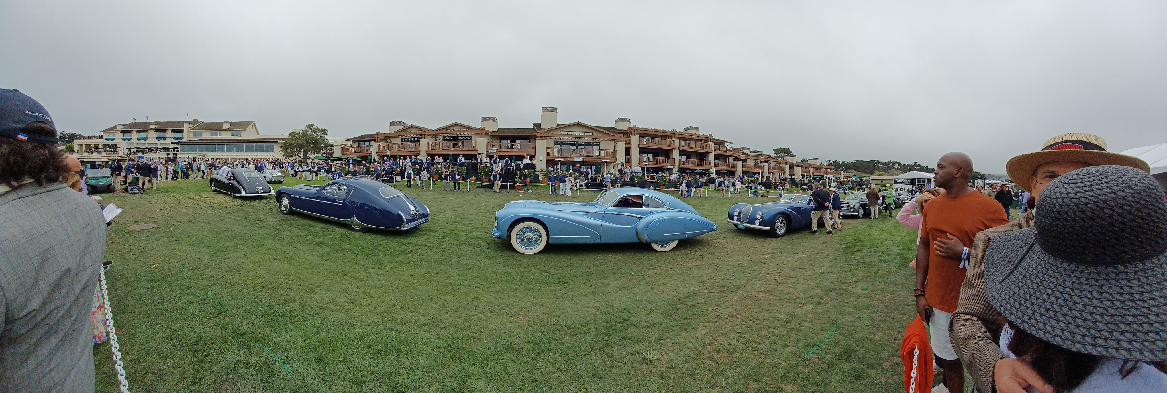
It was great to see then, when I arrived through the throngs of people at the entry to the Green, that the Talbot was in line with the rest of its class to start the awards ceremony with a parade across the podium. In the end, it won second in class and everyone seemed quite pleased with the outcome. I certainly am very happy to see such a positive conclusion, and congratulations to the whole crew out in Colorado! Well done.

Leave a Reply