I have worked on many Bugattis over the last twenty years, but it is important to note that I am not precisely a “specialist”, in the sense of a person who ONLY handles a single brand. I’ve always favored variety in the type of jobs that I take on and I also adore certain Alfa Romeos and Maseratis (and the odd Austin Healey).
When I find myself writing an article about something as obscure as the De Ram shock absorber, I end up learning more through my research than I knew at the time I was doing the work!
A perfect example is the question of which Bugatti models had the aluminum-case De Rams on the front. My first-hand experience with the Type 57 was that most of the cars I dealt with had the steel-bodied De Rams all ’round. The Type 59 that I worked on also had steel-bodies at the front. And then there was the one example with tube shocks.
The Different types of De Rams
The answer was revealed when I belatedly realized that the aluminum-bodied units were made to integrate rubber engine mounts. A bronze casting bolted to the top of the frame member carried the engine mounting bolt through a large bushing clamped in the De Ram body. So there was a period when both the standard 57 chassis and the 57S used the rubber isolated engine mounts, and those would have had the aluminum De Rams. This Series II version of the 57 chassis came in 1936 and went until some point in 1938 when the Series III cars got tubular telescoping shocks.
The earlier Series I chassis had the steel-bodied De Rams, but there was some time period in the beginning when the cars left the factory with the Hartford-type friction dampers. I have no experience with those cars and pictures are hard to come by.
I would love to have been a fly on the wall when Ettore Bugatti and his son Jean were debating the merits of the new telescoping dampers, a device about 100 times less complex than the De Ram, and cheaper by a larger percentage!

This Type 57SC has the steel-bodied front De Rams, with the rigidly mounted engine 
A Series II Type 57S Atalante with an aluminum-case front De Ram damper ahead of the generator. 
This Bugatti Type 57SC Corsica has the aluminum-bodied De Rams in front 
This is a late Bugatti Type 57C with tubular front shocks. Note the steel cross-member added ahead of the engine to stiffen the chassis after rubber mounts replaced the De Rams
Special tools
As previously mentioned in part one, a number of special tools are required to get inside the De Ram damper and to work with them
- 4-pin spanner to remove the main side cover
- Fine-spline tool for the top cap
- Fine-spline tool to remove outer hub retaining ring
- Coarse-spline tool to remove disc outer carrier to housing
- Plate bolting to main body bolt circle to hold unit in bench vise
- Threaded bung to fit into top of body, alternate means of holding in vise
The 4-pin spanner is a heavy-duty item that must be able to withstand hammer blows. There is a hole in the center for a bolt to secure the spanner to the cover in some cases, but in others a large C-clamp can be used to secure it to the cover plate. The pin holes in the cover plate are often badly molested from people using a punch to undo the threads instead of the proper tool. In rare cases, you may have to dig lead solder out of the pin holes before you begin.
Why did they fill the holes with solder? The rear shocks are buried inside the frame, so it cannot be for cosmetic reasons. The front shocks are sandwiched between the engine and an engine mount casting, so again, you can’t see the holes. It must have been to dissuade non-authorized mechanics from getting inside.

This rear De Ram unit still has lead filling the pin holes in the cover, which must be dug out. 
This unit illustrates the damage to the pin holes from using the wrong tool. This cover is also threaded in the center to allow the pin wrench to be bolted to the cover. 
The four-pin wrench fitted to the cover, held in place with a C-clamp to prevent the pins from slipping out.
Before attacking the side cover, it is best to first drain the unit. The top filler cap has its own special spline tool to remove it, then invert the unit and push the operating arm through its travel several times to help move the oil. Removing the adjustment valve body can help get the oil out, and this is located in the top cavity on front units. As it rotates with the central hub, you will need to turn the lever arm until it appears in the window to remove it. On the rear, the valve is in the side of the unit, a plug filling the port in the top cavity. Photos of various valve assemblies were in part one of this story.
With the shock body bolted to the mounting plate tool and secured in a serious vise, the 4-pin spanner is secured to the cover and hit counter-clockwise to loosen the cover in the conventional direction. Before letting it come all the way off, it’s sensible to take it out of the vise and lay it horizontal to prevent the needle rollers from escaping to dark hidden areas under the bench.
Once the side cover is off, the clutch pack is exposed. Usually there is a wire circlip that secures the stack of discs in place, though not always. The discs alternate between steel and bronze, often with some amount of steel shim packing for preload.

The hydraulic mechanism is convoluted because rather than the pistons pushing directly on the clutch pack to squeeze the plates together, they push on a plate that uses four steel links to PULL the stack of discs together. Below the last disc in the stack is a heavier plate that the link bars pull on, which force the disc stack against the friction surface on the outer cover plate. Convoluted!
Some of the link bars are milled from a solid steel block, and some are made of thin sheet stampings that are welded together in a stack.

There may be two small holes in the piston plate, which is what I call the plate that the twelve or eight small pistons work against. These can be used to screw the piston plate down against the pistons, which is useful in assembly.

This unit has two screws holding the piston plate down. After assembling the disc stack and fitting the wire circlip, the screws are removed. 
This De Ram from a Type 59 does not have the 2 small screw holes in the piston plate 
When the plate is removed, you see the 12 pistons are installed upside down, with no preload springs fitted 
This unit had springs behind all 12 pistons, and you can see how much taller they sit compared to the previous image 
Here is another configuration. 3 of the pistons have much longer springs while the other 5 are inverted. This one has two threaded holes to secure the piston plate on assembly.
In the example with no preload springs, I think a downside is that the pistons have to travel to take up free play before they begin to squeeze the disc pack. So there would be some dead space where the hydraulics didn’t do anything, only the preload on the disc stack making them work. I imagine the pistons jumping around, clattering between the hub and the piston plate as the car goes over small bumps, then when it hits a bigger one, all of a sudden the stack gets squeezed tightly. That must feel weird from the driver’s seat.
Going Deeper inside
Once the disc stack and small pistons are removed, the disc hub is retained by a threaded ring on the opposite side from the main cover. This is removed with a fine splined tool that can be forced into the splines by pulling it tightly with the bolt that attaches the operating arm, or the long stud on some front units.

This threaded piece secures the hub to the body, locates the outer needle bearing race, and also seals the oil into the unit. Look at how fragile that spline is! 
This is the tool to remove the splined ring, secured with the bolt that attaches the lever arm 
The splined tool required to unscrew the outer ring. A different version on the table to the right.
There is also a set-screw inside the top oil filler that secures the cam ring in place. Once that is removed and the outer ring is off, the hub can be withdrawn with the cam and the needle bearings will be exposed.
Then the cam is removed from the hub and the main piston and roller can be withdrawn. The complicated hub section has a number of oil ports in it, one of which is permanently staked in place. It also has a bronze thrust surface that is staked in place to take side loads, a part that I have seen come detached on at least one damper.


The outer splined ring that the bronze discs locate in is removed with another special tool, multiple versions of which are possible. This one was particularly nice to use, fitting precisely in the mating part and applying force evenly. At Reilly’s we had new bronze friction discs laser cut, and we made this steel spline for the tool at the same time.


Things that Go Badly
I’ve seen a fair amount of trauma inside these components, most of which I suspect is the result of improper setup. You only have to look at the size of the clutch pack, with the huge surface area available, to imagine how much torque these things are capable of braking. If the adjusting valve is set too tightly, or debris has blocked the port, the clutch pack is effectively locked solid when it is pressurized by a big suspension hit. That can destroy internal parts.
Piston Roller Wheel
One of the sets I serviced had broken the roller that is moved by the cam to activate the main piston. Was this a defective part, the heat treat making it too brittle? Or was it a setup error? Hard to say.


Damaged cams
The same force that broke the roller wheel is also trying to smash the steel face of the cam ring that the roller works against. More than one unit has had damaged cam faces that needed tuning up.

Worn Hub Splines
Much like a clutch basket on a motorcycle engine, the clutch plates can wear notches in the splines over time. On the De Ram, the inner hub splines are more vulnerable because the steel discs are working in the spline. The outer spline carries the bronze discs, which are less likely to wear on the harder steel splines. I have not seen wear bad enough to make them stop working, but a tuneup with a file is often required.

Smashed Radial Splines
All of the work that these mechanisms do is transmitted from the axle into the damper by the lever arm, which is connected to the inner hub by a series of very fine radial splines. These allow precise adjustment of the arm to ensure that the roller is positioned on the cam correctly when the car is sitting at ride height. But if the thread that draws the two parts together gets loose, the splines turn into a milling machine and try to cut one another flat.


Bent pieces
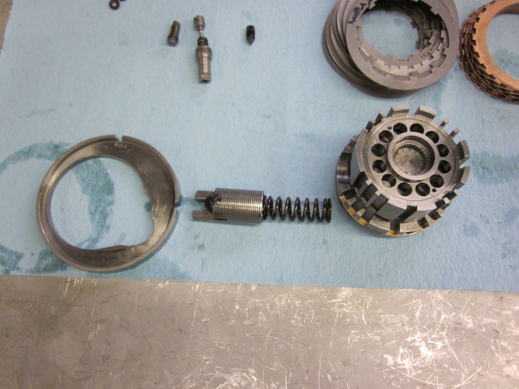
The threaded ring that secures the hub into the body is often damaged from being mishandled. This is a problem because the part is responsible for sealing the oil inside, with a spring steel diaphragm that is staked into the body leaning against a fiber washer carried on this ring.

Rounded off splines… smashed and bent… this part was a mess 
This shows the spring steel diaphragm that the ring seals against. There is a round steel mandrel being applied here to tweak the shape of the seal surface. 
This is the outer ring, held in the splined assembly tool, with a white Teflon seal ring to replace the harder fiber original
Intentional Engineering Choices
Here is a De Ram from a car that sold for many millions of dollars. Somewhere along the line, a caretaker got the idea to gut the mechanism and throw it in the trash, then manufacture a Hartford-style shock inside the housing. A winning idea or a travesty?

From Friction and Hydraulic to Electronic
When setup exactly right, with the best parts and the most skilled hands, these units perform about as well as a 50 dollar shock from Napa Auto Parts. Then again, consider that the recent generation of Bugatti hypercars, the Chiron Pur Sport uses tubular shocks that are little different in concept from the ones on a Series III Type 57 from 1938. Of course, they have electronic damping control integrated with the cars’ ECU, and four adjustable ride height modes.
Bugatti probably sold in the neighborhood of 400 cars with these contraptions, and there are fewer still in circulation today. Georges De Ram’s design was a deeply creative attempt to solve an engineering problem, and it stands alone in history as a bridge between eras of suspension design.
The devices remain fascinating, and exploring the evolution of technology like this, and the histories of the people that made them, is a pursuit that I enjoy greatly.
Do you have any questions about the parts described here, have information to add or tips to share? Please use the comment form below, and hit the subscribe button to get notified when the next One Day in the Shop article comes online.
Leave a Reply