Bugatti Type 35 Grand Prix engines are well known for their complex roller bearing crankshafts, built up from hundreds of components, a design intended to reduce friction losses and to be able to survive on very little oil at very high RPM. 7,000 revs in 1924 was earth shattering. And as far as I know, they were the only manufacturer to use an assembly method that used bicycle cotter pins to hold a crankshaft together.

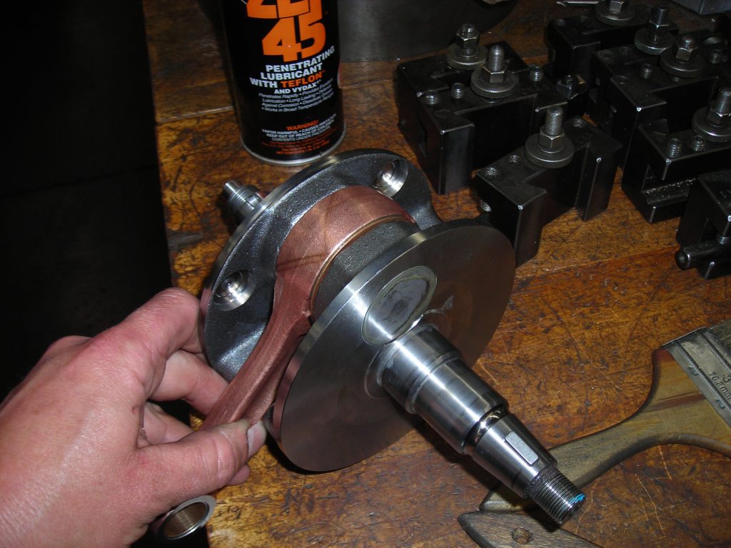
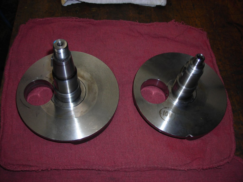
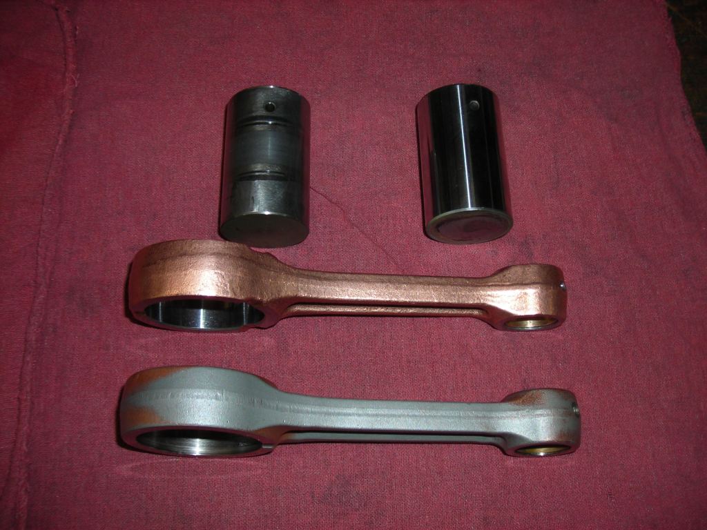
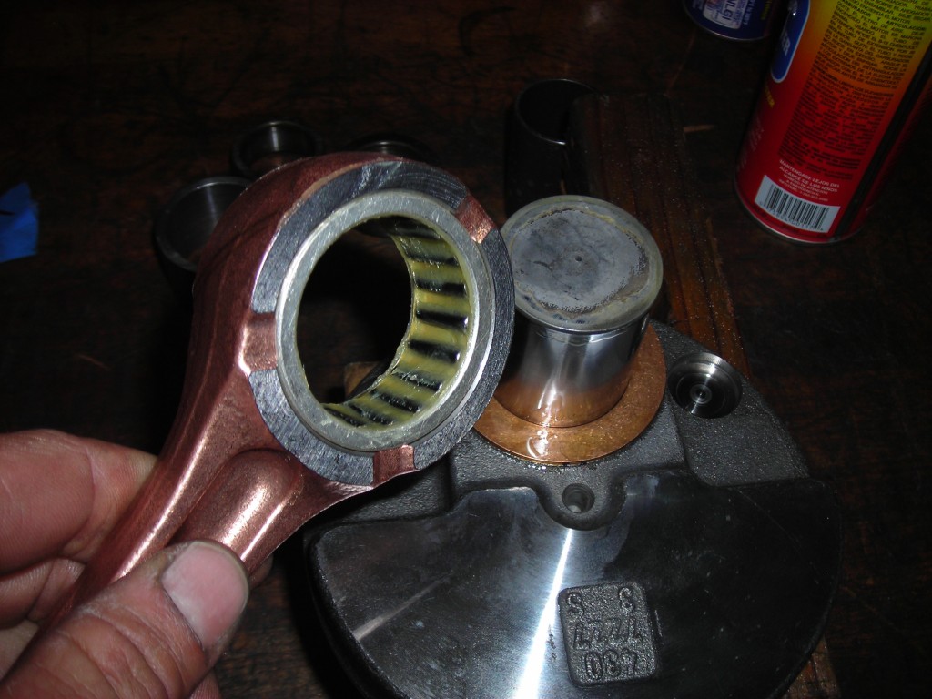
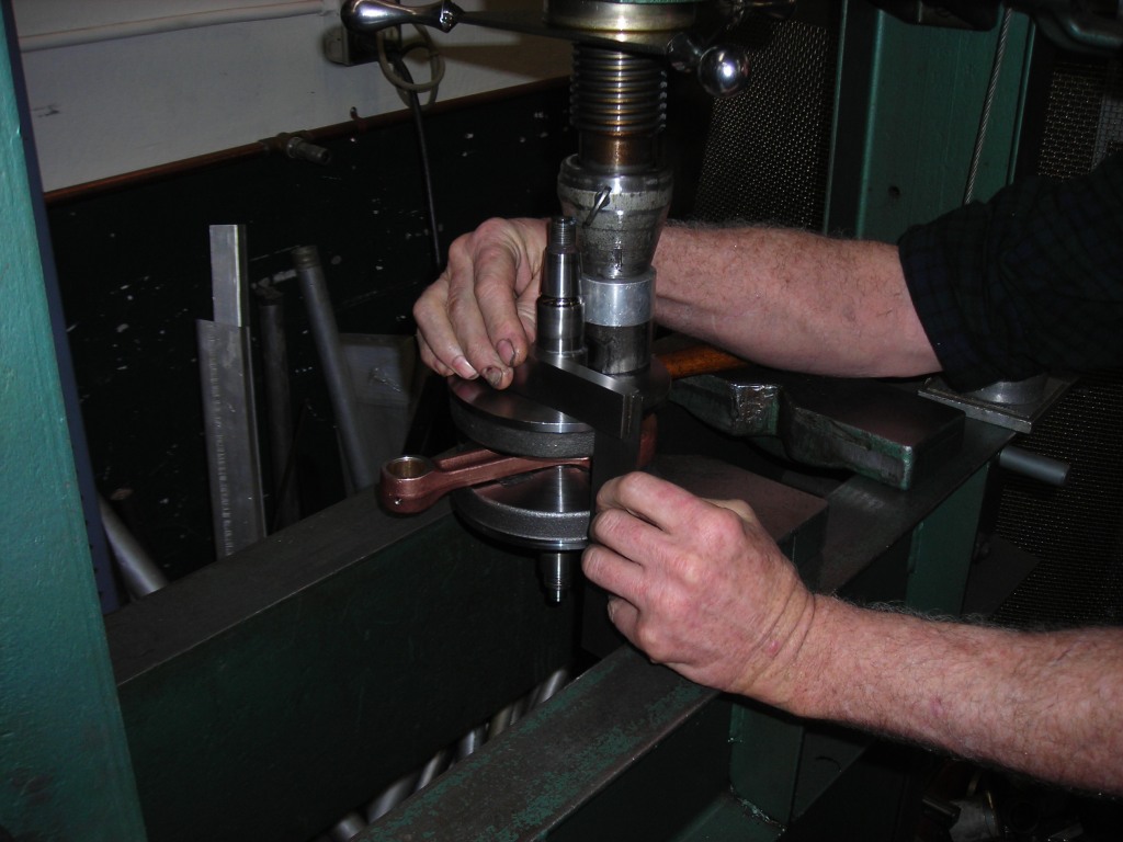
The simplest version of a built-up roller bearing crank is a single cylinder motorcycle engine, with two flywheels or webs and a pressed-in crankpin. I once rebuilt a crankshaft for my KTM 690 Duke, and those pictures illustrate the design pretty well.
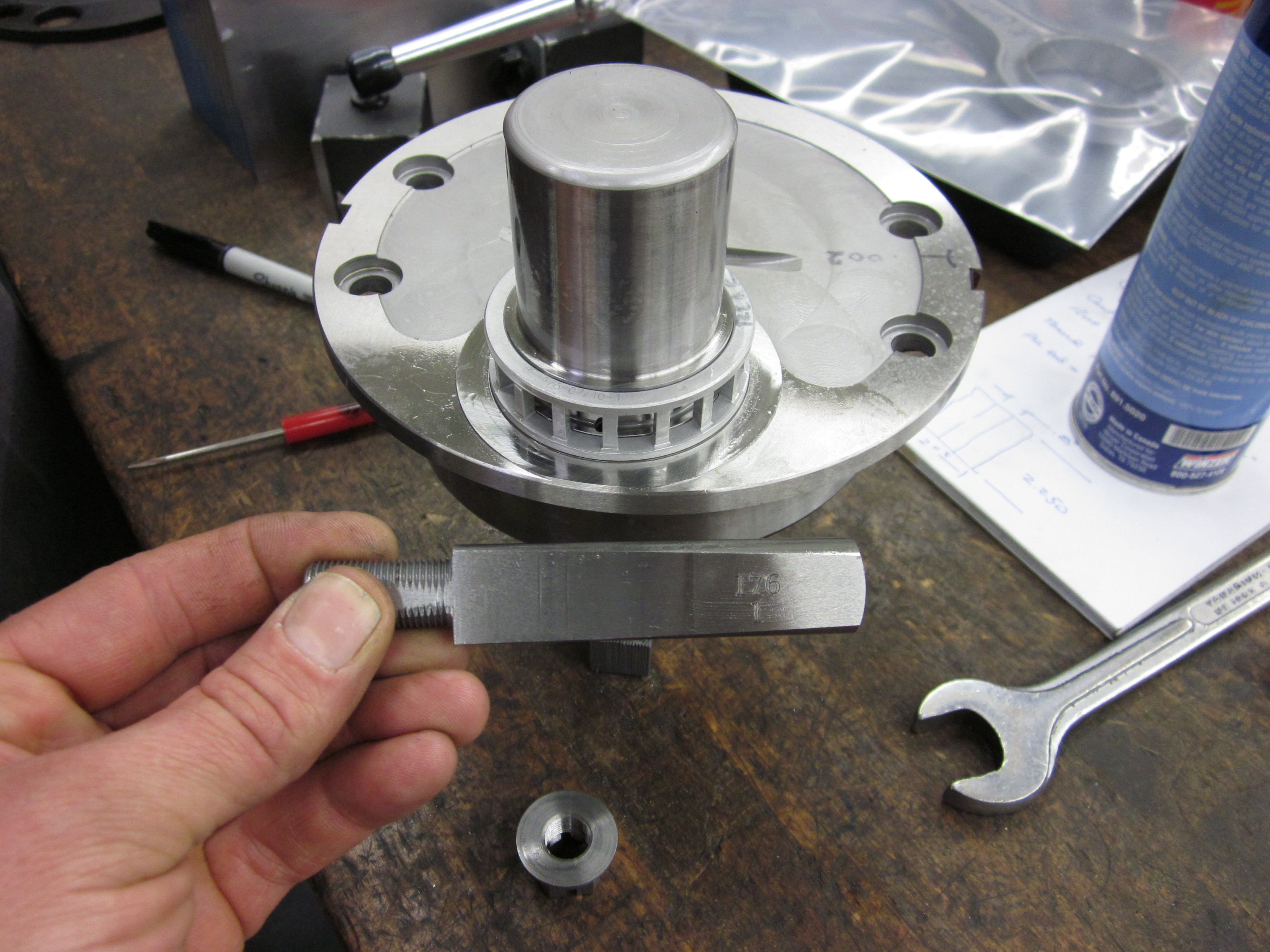
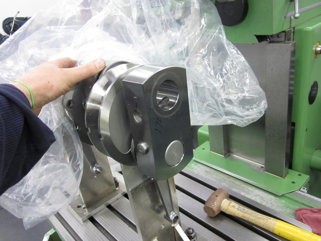
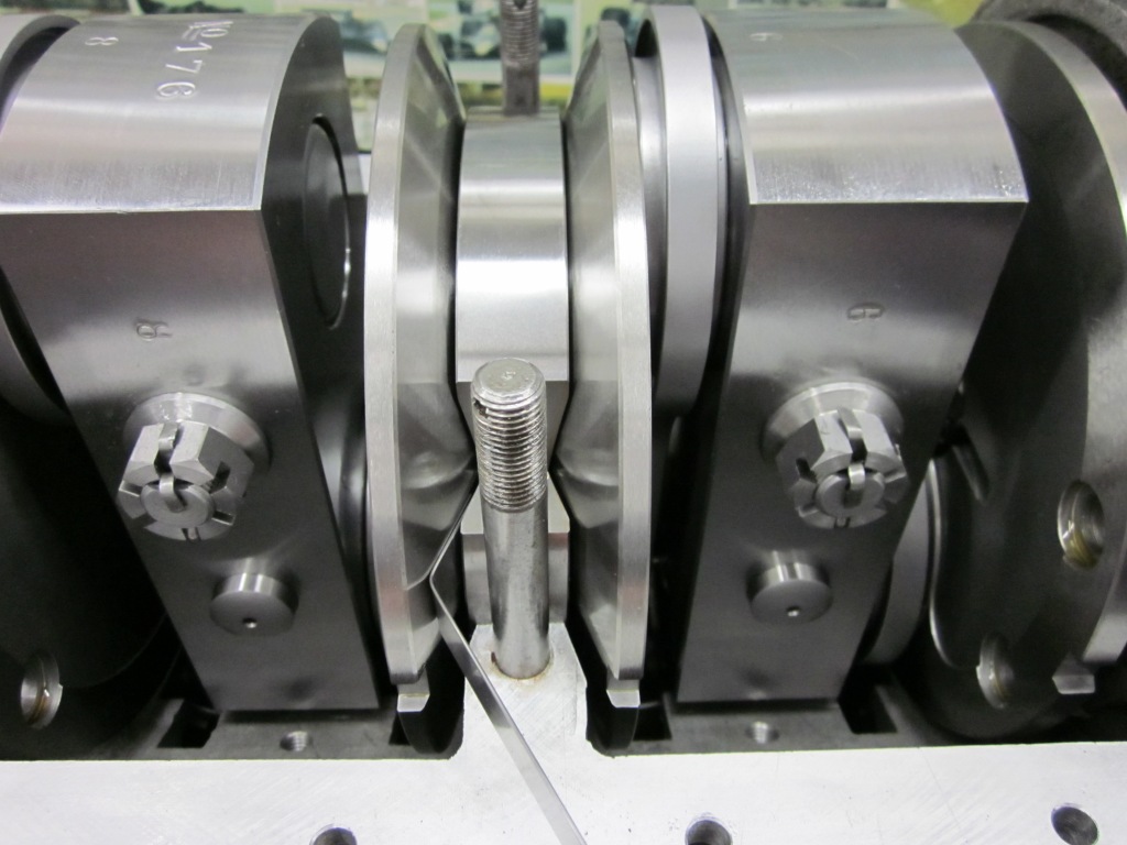
Ettore Bugatti built the T35’s long eight cylinder crank quite differently. Each cylinder’s crankpin was machined in-unit with a web from a single billet of steel, with the opposite web (a block, really) being drilled to accept the free end of the pin, on a slip fit. The crankpin had a flat machined on it, which intersected a cotter pin driven in to make the joint solid.
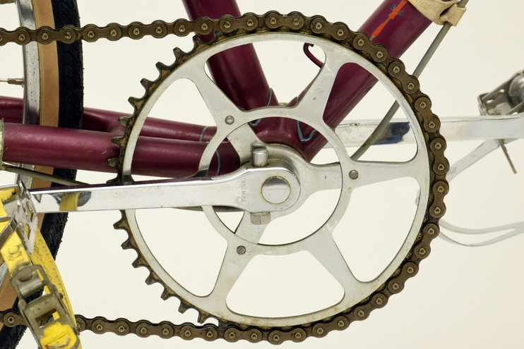
Cotter pins are a very old technology, if that word can be used for such a simple mechanism, which is basically two separate pieces with a wedge driven through to make them a solid unit . Steam engines and trains used them liberally, though I suspect Bugatti took the idea from the world of bicycles. Ettore had worked for a bicycle manufacturer when he was 17 years old, so it may have seemed reasonable to use the same technique that bicycles used to join their cranks together for a machine that would eventually generate well over 150 horsepower!
When a simple crank like my KTM 690 is pressed together, the tricky bit is to get the two webs onto the pin so that they are dead square to the centerline of the main bearings. After using the hydraulic press to force the pin through the webs, the unit is checked for concentricity and adjusted with carefully placed blows from a copper hammer. Only the tightness of the press fit prevents the webs from moving on the pin and losing concentricity. In use, the engine’s torque that goes to the ground out of one end of the crank is trying to twist the crank, and the press fit is what keeps it from twisting. Bugatti decided to use cotter pins to securely fix the web to the crankpin, keeping it from twisting.
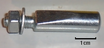
Bicycle cotters are simply straight steel shafts with an angled flat cut on one side, which makes it into a wedge, intersecting the flat cut on the axle. A thread with a nut retains the pin from getting loose, but the wedge is driven together with a hammer and drift. On a simple bicycle crank, the cotter on each side must have the same angle to put the pedals exactly 180 degrees from each other on the axle (or crankpin). I’ve read that it is common with vintage bikes to have to file the angle on the cotters to account for manufacturing tolerances, and the same issue exists with the Bugatti crankshaft.

If you were to bolt up a section of the crank with two exact duplicate cotter pins and in measuring it found it was not square, you would need to change a cotter pin’s angle slightly to re-clock the web closer to on-center. So back at the factory in the ‘20s the crank assembly shop probably had a wall of pins to choose from that each had a slightly different angle. I’m sure they cheated now and then, after a long lunch with too much vino perhaps, and used a belt sander to change the angle.
This is why there are only a handful of people on Earth that will take on the job of rebuilding a Bugatti crank. My old workplace in California, Phil Reilly & Co, tried one time. Legend has it, it took so long and was so frustrating to achieve a good result, that they never signed on for that job again. Fortunately, Brineton Engineering in the UK was still producing new Type 35 cranks while I was there. (Brineton has since sold their business to Tula Precision, though I haven’t had the chance to use them since).
I’ve installed a few new or rebuilt (in England) cranks into type 35 variants, and just that installation is incredibly tricky. There is a very small amount of space to play with when positioning the crank fore and aft in the crankcases, and there are several critical factors determining where it wants to live.
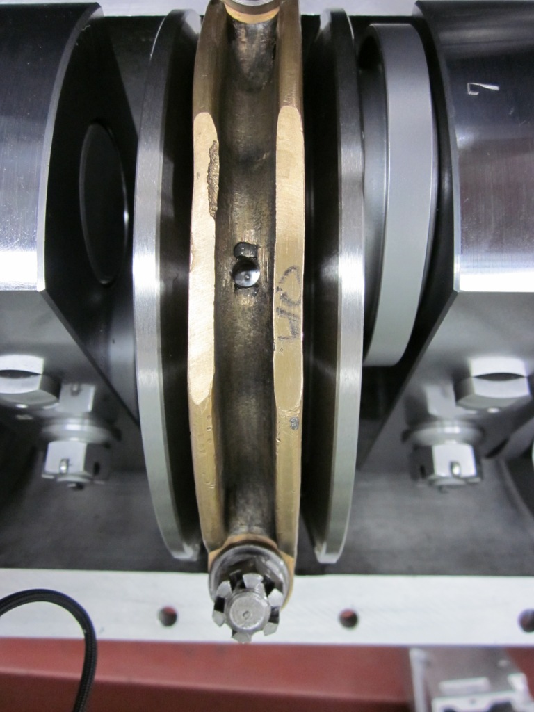
The conrods being centered in the bores, number one. There is some amount of end float on the crankpins for the rod to do a bit of self centering, but you must check that the top end of the rod has room fore and aft inside the piston. It isn’t uncommon to need to machine some material from between the piston pin bosses to make more clearance, Clarence.

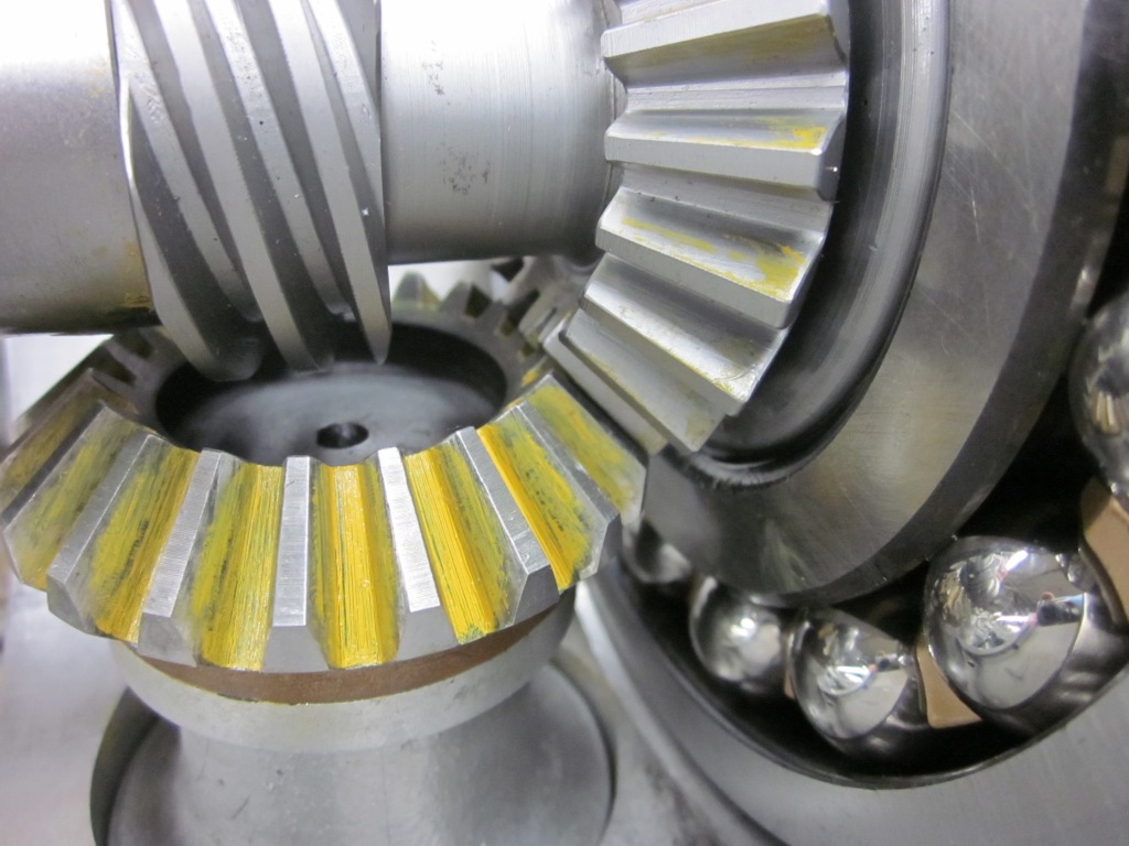
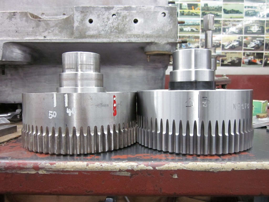
The cam drive at the front of the motor is a pair of bevel gears, and there needs to be a certain amount of gear lash. Two new cranks that I’ve fitted needed the front section disassembled to reposition the gear, which isn’t terribly complicated, but time consuming.
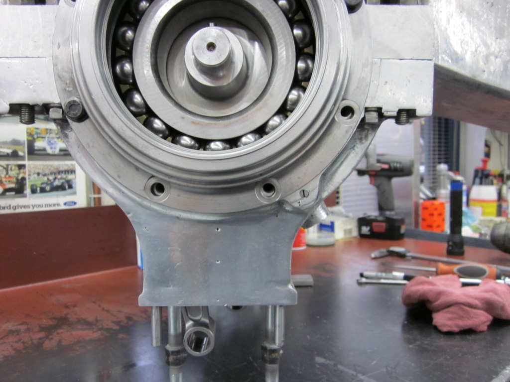
One of the hard limits in positioning the crank is that the rods are fed by oil squirters that feed an annular groove in the web, with a drilling that centrifuges the oil to the rod bearing. The squirters are extremely close to contacting the crank!

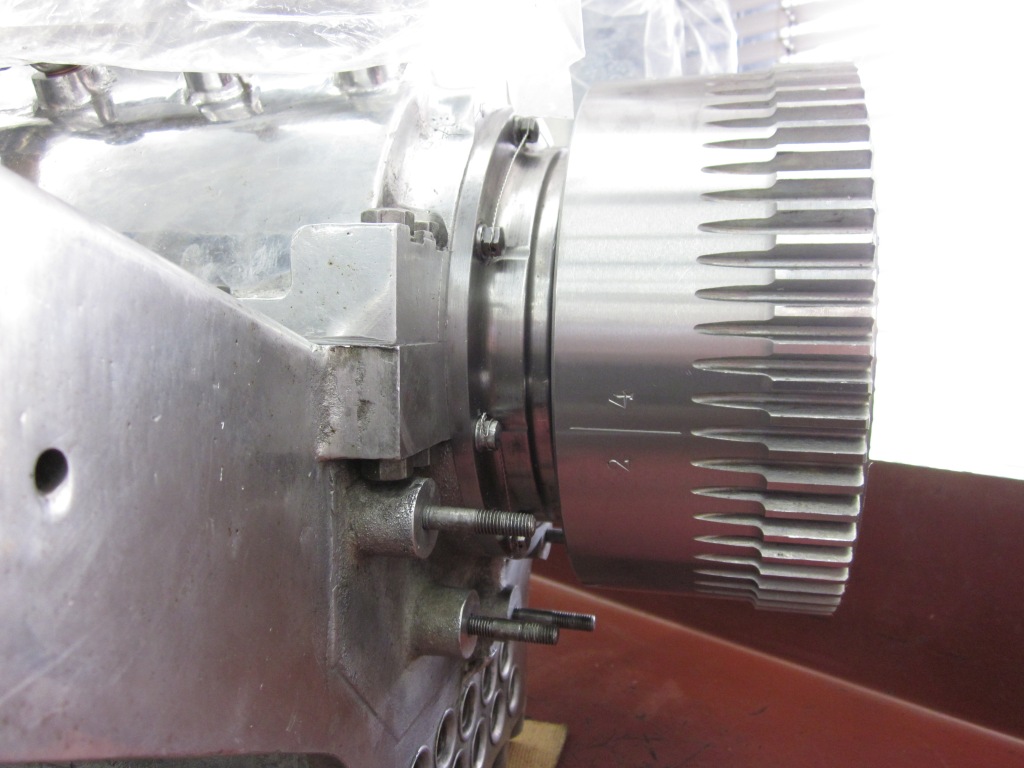
To add complexity to the whole situation, the final position of the crank is determined by the rear bearing carrier on the tail section, which is integral with the flywheel. A nut at the rear end draws the bearing/housing/flywheel package up tight, onto a large taper off the back of the final crank web.
The flywheel is a substantial chunk of metal, but it is possible to fit it onto the taper with a light hand or a heavy hand, and each will put it to a different location . And as the new taper surfaces bed in over several trial fittings, it will seat farther on the taper each time.
So in the end, you have a precisely ground spacer ring in the rear housing that positions the crank fore and aft, and you have a front casting that needs to meet the bearing at the head of the crank with the right amount of squeeze. I’ve heard one expert say they like as much as .007” of preload squeeze, which seems a bit much for me, but the whole assembly grows as it gets to running temperature, and you need to guess how much more the aluminum crankcases will grow relative to the crankshaft itself. You certainly do not want the crank to be able to move around when fully hot, but by the same token, the last thing you want is to have the bearings squeezed too tightly… so pick a number plus or minus half a hairs’ breadth… Fun!

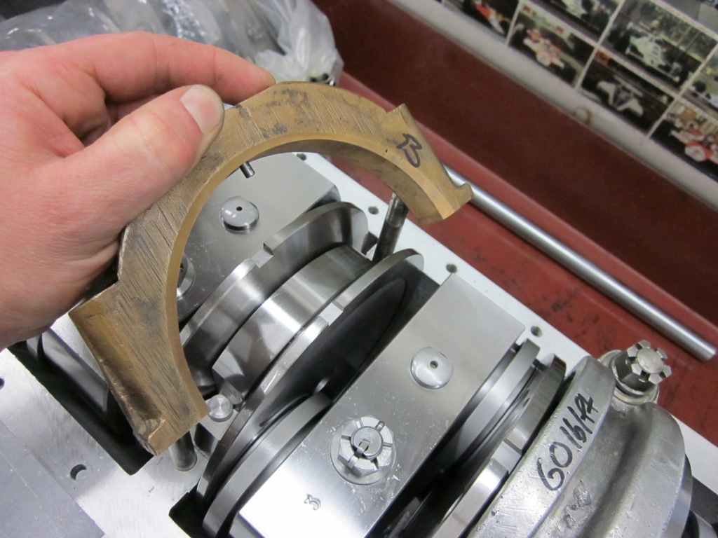
Each of the three huge double row ball bearings on the crank has some amount of end float, and the two intermediate roller bearings have no fore-aft restriction other than the crank webs that surround them. Once the crankshaft has been finally located fore and aft by the front and rear housings, the roller bearing housings need to be located, as they are clamped in place with bronze caps with a pin for radial and axial location.
The two roller bearing housings get disassembled so that the locating hole can be drilled, and then a thorough cleaning is required before final assembly can be contemplated.
This is really just part one of a long complicated process to put one of these motors together. Making sure the oil gets where it is supposed to go, and in the right amount, is the next most crucial goal. The oil pump, the galley pipe and all its nozzles aiming at the bearings and pistons… the cam drive and the gyrations required to get the cam timing on target (which also involves bicycle cotter pins)… it seems unending at times.

But I’m forever grateful that I fell into this career, fate or good fortune, no matter.


Leave a comment